Uses
3D modelers are used in a wide variety of industries. The medical industry uses them to create detailed models of organs. The movie industry uses them to create and manipulate characters and objects for animated and real-life motion pictures. The video game industry uses them to create assets for video games. The science sector uses them to create highly detailed models of chemical compounds. The architecture industry uses them to create models of proposed buildings and landscapes. The engineering community uses them to design new devices, vehicles and structures as well as a host of other uses. There are typically many stages in the "pipeline" that studios and manufacturers use to create 3D objects for film, games, and production of hard goods and structures.
[edit]
Features
Many 3D modelers are general-purpose and can be used to produce models of various real-world entities, from plants to automobiles to people. Some are specially designed to model certain objects, such as chemical compounds or internal organs.
3D modelers allow users to create and alter models via their 3D mesh. Users can add, subtract, stretch and otherwise change the mesh to their desire. Models can be viewed from a variety of angles, usually simultaneously. Models can be rotated and the view can be zoomed in and out.
3D modelers can export their models to files, which can then be imported into other applications as long as the metadata is compatible. Many modelers allow importers and exporters to be plugged-in, so they can read and write data in the native formats of other applications.
Most 3D modelers contain a number of related features, such as ray tracers and other rendering alternatives and texture mapping facilities. Some also contain features that support or allow animation of models. Some may be able to generate full-motion video of a series of rendered scenes (i.e. animation).
Wednesday, December 29, 2010
List of CAx companies
List of CAx companies and their software products. Software using computer-aided technologies (CAx) has been produced since the 1970s through to the present for a variety of computer platforms. This software may include applications for Computer-Aided Design (CAD), Computer-aided engineering (CAE), Computer-aided manufacturing (CAM) and Product Data Management (PDM).
The list is far from complete or representative as the CAD business landscape is very dynamic: almost every month new companies appear, old companies go out of business, companies split and merge. Sometimes some names disappear and reappear again.
The list is far from complete or representative as the CAD business landscape is very dynamic: almost every month new companies appear, old companies go out of business, companies split and merge. Sometimes some names disappear and reappear again.
This list is sorted by company name. Refer to: Category:Computer-aided design software , Category:Computer-aided manufacturing software and Category:Computer-aided engineering software for lists sorted by software name .
Electronic design automation
Electronic design automation (EDA or ECAD) is a category of software tools for designing electronic systems such as printed circuit boards and integrated circuits. The tools work together in a design flow that chip designers use to design and analyze entire semiconductor chips.
This article describes EDA specifically with respect to integrated circuits.
Before EDA, integrated circuits were designed by hand, and manually laid out. Some advanced shops used geometric software to generate the tapes for the Gerber photoplotter, but even those copied digital recordings of mechanically-drawn components. The process was fundamentally graphic, with the translation from electronics to graphics done manually. The best known company from this era was Calma, whose GDSII format survives.
By the mid-70s, developers started to automate the design, and not just the drafting. The first placement and routing (Place and route) tools were developed. The proceedings of the Design Automation Conference cover much of this era.
The next era began about the time of the publication of "Introduction to VLSI Systems" by Carver Mead and Lynn Conway in 1980. This ground breaking text advocated chip design with programming languages that compiled to silicon. The immediate result was a considerable increase in the complexity of the chips that could be designed, with improved access to design verification tools that used logic simulation. Often the chips were easier to lay out and more likely to function correctly, since their designs could be simulated more thoroughly prior to construction. Although the languages and tools have evolved, this general approach of specifying the desired behavior in a textual programming language and letting the tools derive the detailed physical design remains the basis of digital IC design today.
The earliest EDA tools were produced academically. One of the most famous was the "Berkeley VLSI Tools Tarball", a set of UNIX utilities used to design early VLSI systems. Still widely used is the Espresso heuristic logic minimizer and Magic.
Another crucial development was the formation of MOSIS, a consortium of universities and fabricators that developed an inexpensive way to train student chip designers by producing real integrated circuits. The basic concept was to use reliable, low-cost, relatively low-technology IC processes, and pack a large number of projects per wafer, with just a few copies of each projects' chips. Cooperating fabricators either donated the processed wafers, or sold them at cost, seeing the program as helpful to their own long-term growth.
Hackerspace
A hackerspace or hackspace (also referred to as a hacklab, makerspace or creative space) is a location where people with common interests, usually in computers, technology, or digital or electronic art can meet, socialise and/or collaborate. A hackerspace can be viewed as an open community labs incorporating elements of machine shops, workshops and/or studios where hackers can come together to share resources and knowledge to build and make things.[1]
Many hackerspaces participate in the use and development of free software and alternative media and can be found in infoshops or social centers.
The specific activities that take place at hackerspaces vary from place to place. In general, hackerspaces function as centers for peer learning and knowledge sharing, in the form of workshops, presentations, and lectures. They also offer social activities for their members, including game nights and parties. They also provide space for members to work on their individual projects, or collaborate on group projects with other members. Hackerspaces may also operate computer tool lending libraries.[2]
The building the hackerspace occupies is important, because it provides infrastructure that members need to complete their projects. In addition to space, many hackerspaces provide power, servers and networking with Internet-connectivity, audio equipment, video projectors, game consoles, electronics for hacking, and various tools for electronics fabrication and building things.[3]
Fab lab
A Fab Lab (fabrication laboratory) is a small-scale workshop with an array of computer controlled tools that cover several different length scales and various materials, with the aim to make "almost anything". This includes technology-enabled products generally perceived as limited to mass production.
While Fab Labs have yet to compete with mass production and its associated economies of scale in fabricating widely distributed products, they have already shown the potential to empower individuals to create smart devices for themselves. These devices can be tailored to local or personal needs in ways that are not practical or economical using mass production.
While Fab Labs have yet to compete with mass production and its associated economies of scale in fabricating widely distributed products, they have already shown the potential to empower individuals to create smart devices for themselves. These devices can be tailored to local or personal needs in ways that are not practical or economical using mass production.
The fab lab program was started in the Media Lab at MIT, a collaboration between the Grassroots Invention Group and the Center for Bits and Atoms (CBA) at the Massachusetts Institute of Technology, broadly exploring how the content of information relates to its physical representation, and how a community can be powered by technology at the grassroots level. While the Grassroots Invention Group is no longer in the Media Lab, The Center for Bits and Atoms consortium is still actively involved in continuing research in areas related to description and fabrication but does not operate or maintain any of the labs worldwide (with the exception of the mobile fab lab).
The fab lab concept also grew out of a popular class at MIT (MAS.863) named "How To Make (Almost) Anything". The class is still offered in the fall semesters.
There are currently (July 2010) 45 labs in 16 countries:[1]
Direct digital manufacturing
Direct digital manufacturing sometimes calls Rapid, Instant, or On-Demand Manufacturing is a manufacturing process which creates physical parts directly from 3D CAD files or data using computer-controlled additive fabrication techniques without human intervention, also called 3D printing or rapid prototyping. When a small low cost device is used it is also called desktop, or personal manufacturing. The primary distinction between the use of other terms to describe 3D printing is that additive freeform fabrication is solely intended to describe a 3D printed part that is to be used as the final product with minimal post-processing. Whereas other terms used to describe rapid prototyping, additive freeform fabrication and the like are simply alternative ways of describing the 3D printing process itself.
Additive manufacturing is also referred to as Additive Freeform Fabrication, Rapid Prototyping, Layered manufacturing or 3D printing. This technique physically constructs or manifests 3D geometries directly from 3D CAD. The history of the process begins in the mid-1980s. It was originally known as Rapid Prototyping because the technology was used to make prototypes of parts without having to invest the time or resources to develop tooling or other traditional methods. As the process and quality controls have evolved, the market for additive manufacturing has grown to include production applications.
Additive Manufacturing or Direct Digital Manufacturing is an extension of Rapid Prototyping to real parts for use as final products (not prototypes). As of 2010, the equipment has become competitive with traditional manufacturing techniques in terms of price, speed, reliability, and cost of use. This has led to the expansion of its use in industry. There has been explosive growth in the sales and distribution of the hardware. A new industry has emerged to create software to enable more effective use of the technology, one use of which is the customization of products for consumers. The number of materials that the industry uses increased greatly in the decade to 2007.[1] Modern machines can utilize a broad array of plastics & metals.
As the speed, reliability, and accuracy of the hardware improves, additive manufacturing may replace or complement traditional manufacturing in creating end-use products. One advantage often cited is that Additive manufacturing eliminates much of the labor associated with traditional manufacturing. Another often cited example is that production can make any number of complex products simultaneously so long as the parts will fit within the build envelope of the machine.
One of the main technologies used for additive manufacturing is Selective laser sintering, a process which uses laser energy to fuse material to create a solid object. Another technology is called Fused Deposition Modeling (FDM), which is commonly used for rapid prototyping but is becoming more and more popular in direct digital manufacturing.[2]
The use of the technology is likely to grow. In 2007 a sub-$4,000 machine was presented. 3D printing bureaus have sprung up around the globe. The RepRap machine is a do-it-yourself rapid prototyping machine with limited use except for demonstration purposes, however, the machine is cheap to build and is constructed of commonly available materials.
Self-replicating machine
A self-replicating machine is an artificial construct that is theoretically capable of autonomously manufacturing a copy of itself using raw materials taken from its environment. The concept of self-replicating machines has been advanced and examined by Homer Jacobsen, Edward F. Moore, Freeman Dyson, John von Neumann and in more recent times by K. Eric Drexler in his book on nanotechnology, Engines of Creation and by Robert Freitas and Ralph Merkle in their review Kinematic Self-Replicating Machines[1] which provided the first comprehensive analysis of the entire replicator design space. The future development of such technology has featured as an integral part of several plans involving the mining of moons and asteroid belts for ore and other materials, the creation of lunar factories and even the construction of solar power satellites in space. The possibly misnamed von Neumann probe[2] is one theoretical example of such a machine. Von Neumann also worked on what he called the universal constructor, a self-replicating machine that would operate in a cellular automata environment.
A self-replicating machine is, as the name suggests, an artificial self-replicating system that relies on conventional large-scale technology and automation. Certain idiosyncratic terms are occasionally found in the literature. For example, the term "clanking replicator" was once used by Drexler[3] to distinguish macroscale replicating systems from the microscopic nanorobots or "assemblers" that nanotechnology may make possible, but the term is informal and is rarely used by others in popular or technical discussions. Replicators have also been called "von Neumann machines" after John von Neumann, who first rigorously studied the idea. But this term ("von Neumann machine") is less specific and also refers to a completely unrelated computer architecture proposed by von Neumann, so its use is discouraged where accuracy is important. Von Neumann himself used the term universal constructor to describe such self-replicating machines.
Historians of machine tools, even before the numerical control era, sometimes spoke figuratively of machine tools as a class of machines that is unique because they have the ability "to reproduce themselves",[4] by which they meant the ability to make copies of all of their parts. However, implicit in such discussions is the fact that a human would be directing the cutting processes (or, later, at least planning and programming them) and then assembling the parts. The same is true of RepRaps, which are another class of machines sometimes mentioned in reference to such non-autonomous "self-replication". In contrast, machines that are truly (autonomously) self-replicating are the main subject discussed here.
3D printing
3D printing is a form of additive manufacturing technology where a three dimensional object is created by laying down successive layers of material.[1] 3D printers are generally faster, more affordable and easier to use than other additive manufacturing technologies. 3D printers offer product developers the ability to print parts and assemblies made of several materials with different mechanical and physical properties in a single build process. Advanced 3D printing technologies yield models that closely emulate the look, feel and functionality of product prototypes.
A 3D printer works by taking a 3D computer file and using and making a series of cross-sectional slices. Each slice is then printed one on top of the other to create the 3D object.
Since 2003 there has been large growth in the sale of 3D printers. Additionally, the cost of 3D printers has declined.[2] The technology also finds use in the jewellery, footwear, industrial design, architecture, engineering and construction (AEC), automotive, aerospace, dental and medical industries.
Digital materialization
Digital and computer based languages and processes, unlike the analogue counterparts, can computationally and spatially describe and control matter in a exact, constructive and accessible manner. However, this requires approaches that can handle the complexity of natural objects and materials.
Digital Materialization (DM) [1], [2] can loosely be defined as two-way direct communication or conversion between matter and information that enable people to exactly describe, monitor, manipulate and create any arbitrary real object. DM is a general paradigm alongside a specified framework that is suitable for computer processing and includes: holistic, coherent, volumetric modeling systems; symbolic languages that are able to handle infinite degrees of freedom and detail in a compact format; and the direct interaction and/or fabrication of any object at any spatial resolution without the need for “lossy” or intermediate formats.
DM systems possess the following attributes:
realistic - correct spatial mapping of matter to information
exact - exact language and/or methods for input from and output to matter
infinite - ability to operate at any scale and define infinite detail
symbolic - accessible to individuals for design, creation and modification
Such an approach can not only be applied to tangible objects but can include the conversion of things such as light and sound to/from information and matter. Systems to digitally materialize light and sound already largely exist now (e.g. photo editing, audio mixing, etc.) and have been quite effective - but the representation, control and creation of tangible matter is poorly support by computational and digital systems.
Common place computer aided design and manufacturing systems currently represent real objects as "2.5 dimensional" shells. In contrast, DM proposes a deeper understanding and sophisticated manipulation of matter by directly using rigorous mathematics as complete volumetric descriptions of real objects. By utilizing technologies such as Function representation (FRep) it becomes possible to compactly describe and understand the surface and internal structures or properties of an object at an infinite resolution. Thus models can accurately represent matter across all scales making it possible to capture the complexity and quality of natural and real objects and ideally suited for digital fabrication and other kinds of real world interactions. DM surpasses the previous limitations of static disassociated languages and simple human-made objects, to propose systems that are heterogeneous, interacting directly and more naturally with the complex world
Isosurface
An isosurface is a three-dimensional analog of an isoline. It is a surface that represents points of a constant value (e.g. pressure, temperature, velocity, density) within a volume of space; in other words, it is a level set of a continuous function whose domain is 3D-space.
Isosurfaces are normally displayed using computer graphics, and are used as data visualization methods in computational fluid dynamics (CFD), allowing engineers to study features of a fluid flow (gas or liquid) around objects, such as aircraft wings. An isosurface may represent an individual shock wave in supersonic flight, or several isosurfaces may be generated showing a sequence of pressure values in the air flowing around a wing. Isosurfaces tend to be a popular form of visualization for volume datasets since they can be rendered by a simple polygonal model, which can be drawn on the screen very quickly.
In medical imaging, isosurfaces may be used to represent regions of a particular density in a three-dimensional CT scan, allowing the visualization of internal organs, bones, or other structures.
Numerous other disciplines that are interested in three-dimensional data often use isosurfaces to obtain information about pharmacology, chemistry, geophysics and meteorology.
A popular method of constructing an isosurface from a data volume is the marching cubes algorithm.
Examples of isosurfaces are 'Metaballs' or 'blobby objects' used in 3D visualisation. A more general way to construct an isosurface is to use the function representation and the HyperFun language.
Function representation
In computer graphics the function representation (FRep[1] or F-Rep) is used in solid modeling and volume modeling. FRep was introduced in "Function representation in geometric modeling: concepts, implementation and applications" [2] as a uniform representation of multidimensional geometric objects (shapes). An object as a point set in multidimensional space is defined by a single continuous real-valued function of point coordinates F(X) which is evaluated at the given point by a procedure traversing a tree structure with primitives in the leaves and operations in the nodes of the tree. The points with F(X) >= 0 belong to the object, and the points with F(X) < 0 are outside of the object. The point set with F=0 is called an isosurface.
Winged edge
The winged edge data structure is a data representation used to describe polygon models in computer graphics. It explicitly describes the geometry and topology of faces, edges, and vertices when three or more surfaces come together and meet at a common edge. The ordering is such that the surfaces are ordered counter-clockwise with respect to the innate orientation of the intersection edge. Moreover the representation allows numerically unstable situations like that depicted below.
The winged edge data structure allows for quick traversal between faces, edges, and vertices due to the explicitly linked structure of the network. This rich form of specifying an unstructured grid is in contrast to simpler specifications of polygon meshes such as a node and element list, or the implied connectivity of a regular grid.
[edit]
Pseudocode
Here is a data structure suitable for representing a winged edge. The abbreviation "WE" stands for "Winged Edge".
class WE_Edge {
WE_Vertex vert1, vert2;
WE_Face aFace, bFace;
WE_Edge aPrev, aNext, bPrev, bNext; // clockwise ordering
WE_EdgeDataObject data;
}
class WE_Vertex {
List edges;
WE_VertexDataObject data;
}
class WE_Face {
List edges;
WE_FaceDataObject data;
}
The winged edge data structure allows for quick traversal between faces, edges, and vertices due to the explicitly linked structure of the network. This rich form of specifying an unstructured grid is in contrast to simpler specifications of polygon meshes such as a node and element list, or the implied connectivity of a regular grid.
[edit]
Pseudocode
Here is a data structure suitable for representing a winged edge. The abbreviation "WE" stands for "Winged Edge".
class WE_Edge {
WE_Vertex vert1, vert2;
WE_Face aFace, bFace;
WE_Edge aPrev, aNext, bPrev, bNext; // clockwise ordering
WE_EdgeDataObject data;
}
class WE_Vertex {
List
WE_VertexDataObject data;
}
class WE_Face {
List
WE_FaceDataObject data;
}
Solid modeling
Solid modeling (or modelling) is a consistent set of principles for mathematical and computer modeling of three dimensional solids. Solid modeling is distinguished from related areas of Geometric modeling and Computer graphics by its emphasis on physical fidelity [1]. Together, the principles of geometric and solid modeling form the foundation of Computer-aided design and in general support the creation, exchange, visualization, animation, interrogation, and annotation of digital models of physical objects.
Computer-aided design
Computer-aided design (CAD), also known as computer-aided design and drafting (CADD), is the use of computer technology for the process of design and design-documentation. Computer Aided Drafting describes the process of drafting with a computer. CADD software, or environments, provide the user with input-tools for the purpose of streamlining design processes; drafting, documentation, and manufacturing processes. CADD output is often in the form of electronic files for print or machining operations. The development of CADD-based software is in direct correlation with the processes it seeks to economize; industry-based software (construction, manufacturing, etc.) typically uses vector-based (linear) environments whereas graphic-based software utilizes raster-based (pixelated) environments.
CADD environments often involve more than just shapes. As in the manual drafting of technical and engineering drawings, the output of CAD must convey information, such as materials, processes, dimensions, and tolerances, according to application-specific conventions.
CAD may be used to design curves and figures in two-dimensional (2D) space; or curves, surfaces, and solids in three-dimensional (3D) objects.[1]
CAD is an important industrial art extensively used in many applications, including automotive, shipbuilding, and aerospace industries, industrial and architectural design, prosthetics, and many more. CAD is also widely used to produce computer animation for special effects in movies, advertising and technical manuals. The modern ubiquity and power of computers means that even perfume bottles and shampoo dispensers are designed using techniques unheard of by engineers of the 1960s. Because of its enormous economic importance, CAD has been a major driving force for research in computational geometry, computer graphics (both hardware and software), and discrete differential geometry.[2]
The design of geometric models for object shapes, in particular, is often called computer-aided geometric design (CAGD).[3]
Graphics tablet
A graphics tablet (or digitizer, digitizing tablet, graphics pad, drawing tablet) is a computer input device that allows one to hand-draw images and graphics, similar to the way one draws images with a pencil and paper. These tablets may also be used to capture data or handwritten signatures. It can also be used to trace an image from a piece of paper which is taped or otherwise secured to the surface. Capturing data in this way, either by tracing or entering the corners of linear poly-lines or shapes is called digitizing.A graphics tablet (also called pen pad or digitizer) consists of a flat surface upon which the user may "draw" or trace an image using an attached stylus, a pen-like drawing apparatus. The image generally does not appear on the tablet itself but, rather, is displayed on the computer monitor. Some tablets, however, come as a functioning secondary computer screen[1] that you can interact with images[2] directly by using the stylus.Some tablets are intended as a general replacement for a mouse as the primary pointing and navigation device for desktop computers.
Thursday, October 14, 2010
virtual utopias: Snow Crash & Circuit of Heaven
virtual utopias
"virtual" refers to "virtual reality" or "virtual worlds"
Virtual reality--many terms for same development, or different aspects of it
cybernetics, IT (instructional / information technology)
The Matrix
computer-simulated environment
artificial reality
computer graphics
cyberspace, computer-simulated world
wired / wireless world
online


virtual reality: cocooning, infosphere
reality becomes code, data, information
compare Platonism, platonic ideals, simplified geometrical forms
escapes rough edges & messiness of biological existence
virtual reality = technology allowing viewer to interact with simulated environment
HSL and HSV

 |  | |
| HSL cylinder | HSV cylinder |
HSL and HSV are the two most common cylindrical-coordinate representations of points in an RGB color model, which rearrange the geometry of RGB in an attempt to be more perceptually relevant than the cartesian representation. They were developed in the 1970s for computer graphics applications, and are used for color pickers, in color-modification tools in image editing software, and less commonly for image analysis and computer vision.
HSL stands for hue, saturation, and lightness, and is often also called HLS. HSV stands for hue, saturation, and value, and is also often called HSB (B for brightness). A third model, common in computer vision applications, is HSI, for hue, saturation, and intensity. Unfortunately, while typically consistent, these definitions are not standardized, and any of these abbreviations might be used for any of these three or several other related cylindrical models. (For technical definitions of these terms, see below.)
In each cylinder, the angle around the central vertical axis corresponds to “hue”, the distance from the axis corresponds to “saturation”, and the distance along the axis corresponds to “lightness”, “value” or “brightness”. Note that while “hue” in HSL and HSV refers to the same attribute, their definitions of “saturation” differ dramatically. Because HSL and HSV are simple transformations of device-dependent RGB models, the physical colors they define depend on the colors of the red, green, and blue primaries of the device or of the particular RGB space, and on the gamma correction used to represent the amounts of those primaries. Each unique RGB device therefore has unique HSL and HSV spaces to accompany it, and numerical HSL or HSV values describe a different color for each basis RGB space.[1]
Both of these representations are used widely in computer graphics, and one or the other of them is often more convenient than RGB, but both are also commonly criticized for not adequately separating color-making attributes, or for their lack of perceptual uniformity. Other more computationally intensive models, such as CIELAB or CIECAM02 better achieve these goals.
YIQ


YIQ is the color space used by the NTSC color TV system, employed mainly in North and Central America, and Japan. In the U.S., it is currently federally mandated for analog over-the-air TV broadcasting as shown in this excerpt of the current FCC rules and regulations part 73 "TV transmission standard":
| “ | The equivalent bandwidth assigned prior to modulation to the color difference signals EQ′ and EI′ are as follows: Q-channel bandwidth: At 400 kHz less than 2 dB down. At 500 kHz less than 6 dB down. At 600 kHz at least 6 dB down. I-channel bandwidth: At 1.3 MHz less than 2 dB down. At 3.6 MHz at least 20 dB down. | ” |
I stands for in-phase, while Q stands for quadrature, referring to the components used in quadrature amplitude modulation. Some forms of NTSC now use the YUV color space, which is also used by other systems such as PAL.
The Y component represents the luma information, and is the only component used by black-and-white television receivers. I and Q represent the chrominance information. In YUV, the U and V components can be thought of as X and Y coordinates within the color space. I and Q can be thought of as a second pair of axes on the same graph, rotated 33°; therefore IQ and UV represent different coordinate systems on the same plane.
The YIQ system is intended to take advantage of human color-response characteristics. The eye is more sensitive to changes in the orange-blue (I) range than in the purple-green range (Q) — therefore less bandwidth is required for Q than for I. Broadcast NTSC limits I to 1.3 MHz and Q to 0.4 MHz. I and Q are frequency interleaved into the 4 MHz Y signal, which keeps the bandwidth of the overall signal down to 4.2 MHz. In YUV systems, since U and V both contain information in the orange-blue range, both components must be given the same amount of bandwidth as I to achieve similar color fidelity.
Very few television sets perform true I and Q decoding, due to the high costs of such an implementation[citation needed]. Compared to the cheaper R-Y and B-Y decoding which requires only one filter, I and Q each requires a different filter to satisfy the bandwidth differences between I and Q. These bandwidth differences also requires that the 'I' filter include a time delay to match the longer delay of the 'Q' filter. The Rockwell Modular Digital Radio (MDR) was one I and Q decoding set, which in 1997 could operate in frame-at-a-time mode with a PC or in realtime with the Fast IQ Processor (FIQP). Some RCA "Colortrak" home TV receivers made circa 1985 not only used I/Q decoding, but also advertised its benefits along with its comb filtering benefits as full "100 percent processing" to deliver more of the original color picture content. Earlier, more than one brand of color TV (RCA, Arvin) used I/Q decoding in the 1954 or 1955 model year on models utilizing screens about 13 inches (measured diagonally). The original Advent projection television used I/Q decoding. Around 1990, at least one manufacturer (Ikegami) of professional studio picture monitors advertised I/Q decoding.
CMYK color model
 |  | |
| Cyan, magenta, yellow, and key (black). | Layers of simulated glass show how semi-transparent layers of color combine on paper into spectrum of CMY colors. |
The CMYK color model (process color, four color) is a subtractive color model, used in color printing, and is also used to describe the printing process itself. CMYK refers to the four inks used in some color printing: cyan, magenta, yellow, and key black. Though it varies by print house, press operator, press manufacturer and press run, ink is typically applied in the order of the abbreviation.
The “K” in CMYK stands for key since in four-color printing cyan, magenta, and yellow printing plates are carefully keyed or aligned with the key of the black key plate. Some sources suggest that the “K” in CMYK comes from the last letter in "black" and was chosen because B already means blue.[1][2] However, this explanation, though plausible and useful as a mnemonic, is incorrect.[3]
The CMYK model works by partially or entirely masking colors on a lighter, usually white, background. The ink reduces the light that would otherwise be reflected. Such a model is called subtractive because inks “subtract” brightness from white.
In additive color models such as RGB, white is the “additive” combination of all primary colored lights, while black is the absence of light. In the CMYK model, it is the opposite: white is the natural color of the paper or other background, while black results from a full combination of colored inks. To save money on ink, and to produce deeper black tones, unsaturated and dark colors are produced by using black ink instead of the combination of cyan, magenta and yellow.
RGB color model

The RGB color model is an additive color model in which red, green, and blue light are added together in various ways to reproduce a broad array of colors. The name of the model comes from the initials of the three additive primary colors, red, green, and blue.
The main purpose of the RGB color model is for the sensing, representation, and display of images in electronic systems, such as televisions and computers, though it has also been used in conventional photography. Before the electronic age, the RGB color model already had a solid theory behind it, based in human perception of colors.
RGB is a device-dependent color model: different devices detect or reproduce a given RGB value differently, since the color elements (such as phosphors or dyes) and their response to the individual R, G, and B levels vary from manufacturer to manufacturer, or even in the same device over time. Thus an RGB value does not define the same color across devices without some kind of color management.
Typical RGB input devices are color TV and video cameras, image scanners, and digital cameras. Typical RGB output devices are TV sets of various technologies (CRT, LCD, plasma, etc.), computer and mobile phone displays, video projectors, multicolor LED displays, and large screens as JumboTron, etc. Color printers, on the other hand, are not RGB devices, but subtractive color devices (typically CMYK color model).
This article discusses concepts common to all the different color spaces that use the RGB color model, which are used in one implementation or another in color image-producing technology.
Drawing Algorithms and Viewing
Scan converting lines
Basic incremental algorithm
One way for scan conversion of lines is to compute the slope m as dy/dx, to increment x by 1 starting with the leftmost point, to calculate yi = mxi + B for each xi, and intensify the pixel at (xi, Round(yi)), where Round(yi) = Floor(0.5 + yi). This computation selects the closest pixel. This approach can be improved by using dyi+1 = dyi + m (here dx = 1 for each incremental). The illustration is shown below:

To note: if the slope m < 1, the x, y should be reversed.
Midpoint line algorithm
We assume that the lines' slope m is between 0 and 1. For each point P, we observe the next midpoint M, if M lies above line, we choose E, otherwise we choose NE. If E is chosen, M is incremented by one step in the x direction, otherwise we increase M by one step in each direction. The illustration is shown below:

To apply the midpoint criterion, we need to computer F(M) = F(xp + 1, yp + 1/2), if F(M) <>
Scan converting circles
For circles, we can still use incremental algorithm or midpoint algorithm.

Antialiasing
We can find that the results from above algorithm are not so good in most case. To improve the picture quality we apply antialiasing.
Unweighted area sampling
In this technique, we set the pixel intensity proportional to the amount of area covered. The illustration is shown below:

Geometrical Transformations
Affine transformations
Affine transformations have the property of preserving parallelism of lines.
2D Affine transformations
Using homogeneous coordinates, the 2D affine transformations are, respectively,
Translation:
Rotation:

Scaling:

Shear(combination of Rotation and scaling):

Please note the above transformations we use a convention of post-multiplying by column vectors, while the convention of premultiplying by row vectors is used in other places. Matrices must be transposed to go from one convention to another:
(P * M)T = MT * PT
3D affine transformations
Translation:

Rotation:

Scaling:

Planar geometric projections
A thorough review can be found here.

Perspective Projections
Determined by Center of Project
Parallel Projections
Determined by Direction of Projection

Orthographic projections
Top, Front, Side
 Image Courtesy of Brown University
Axonometric (projection plane is not parallel to any of the coordinates planes. For isometric projection, angles between all three principle axes are equal)

Perspective Projection

Representing Curves and Surfaces
Polygon Meshes
Parametric cubic curves
x(t) = axt3 + bxt2 + cxt + dx,
y(t) = ayt3 + byt2 + cyt + dy,
z(t) = azt3 + bzt2 + czt + dz, 0 ≤ t ≤ 1
Hermite Curves
Bézier Curves
Uniform Non rational B-Splines
Non Uniform Non Rational B-Splines
Non Uniform Rational B-Splines (NURBS)
Parametric Bi-cubic Surfaces
Hermite surfaces
Bézier Surfaces
B-Spline Surfaces
What are special effects?
|
| Special effects (SFX) are used in many forms of entertainment such as movies and TV shows to create a more realistic and convincing atmosphere. They are used to portray something that is not possible in today's world - such as the reality of non-existent creatures, or space travel in distant galaxies. They are also used as a matter of convenience when the cost of portraying an image may be too expensive, or too inconvenient - such as creating a five-minute scene on the top of Mt. Everest. Special effects may also be used in order to enhance or augment the quality of an image to create a more realistic experience for the viewer. There are many forms of special effects that have developed over the years. Special effects include the flying image of Peter Pan hanging from a wire in a live-play, gruesome costumes of monsters, and even characters in movies that are completely computer generated. Some basic forms of special effects include: |
|---|
| |
|---|
| On-Stage Techniques These are techniques that take place on the stage are taken for granted today. Examples include an object on the stage of a live-play functioning when it should not be - such as the sound of a hair dryer or toilet flushing. Another example of this are background paintings, which give the impression that an actor is somewhere he is not; again, this is more common on live stage plays. |  |
|---|
 | Filming Techniques Some of these techniques include matte paintings which create a foreground painted on a piece of glass that the camera films through. Also, miniature effects are created by using a small scale model that the viewer is unaware of. |
|---|
| Outward Appearance The most basic of outward appearances is the costume - this is a basic of anything in the entertainment industry. More advanced versions of this include modern prosthetic makeup. Prosthetic makeup is used by creating a mold of a body part (usually the face) and molding it into whatever the artist chooses. This can create amazing appearances of wounds, or non-human features. |  |
|---|
 | Blue Screen The blue screen is a technique that is used by having the actor stand in front of a solid colored blue screen, which is later replaced by the preferred scene. This is often used when the actual background cannot be achieved (due to expensive costs, non-existent realms, etc). With the advent of the digital age, this process has been greatly improved. |
|---|
| Wire Removal Wire removal is often used to create the sensation of a flying actor. The actor is placed in front of a blue screen, and later the wire is digitally erased frame by frame before finally adding in the preferred background. In this way, the viewer will not see the wire holding the actor. |  |
|---|
 | Computer Graphics Now the most prominent of special effects, computer generated images (CGI) are created on a computer through models, hand-drawings, or a filmed scene with live actors. With CGI, artists are able to create a variety of images, experiment with ease, and create movements and interactions that require much less effort and time. |
|---|
Maze complexity and aesthetics: deep problems in computer graphics

Craig S. Kaplan is an Assistant Professor at the Computer Graphics Lab, The David R. Cheriton School of Computer Science, University of Waterloo, Ontario, Canada. Studying the use of computer graphics in the creation of geometric art and ornament, Professor Kaplan's interests extend into non-photorealistic rendering.
I happen know at least two high-end software engineers fighting similar research area and aware of some of its complexities and difficulties. Yet, Professor Kaplan's Maze Design is certainly one of the most spectacular amazing presentations of discrete geometry and non-photorealistic rendering techniques I have ever seen.
Creating computer generated mazes using human designer input, Professor Kaplan and his PhD student, Jie Xu, were interested in two complementary questions with respect to maze design: Complexity and Aesthetics. According to Kaplan computer-based maze design requires a mix of techniques from discrete geometry and non-photorealistic rendering. Thus, the two questions of complexity and aesthetics in mazes both represent profound problems in computer graphics.
Kaplan and Jie Xu were trying to answer the following questions:
Complexity
"What makes a maze difficult to solve? The more we consider this question, the more elusive it becomes. It's certainly possible to begin defining mathematical measures of a maze's complexity, but complexity must depend on aspects of human perception as well. For example, the eye can easily become lost in a set of parallel passages. Complexity also depends on how the maze is to be solved. Are you looking down on the maze, solving it by eye? With a pencil? What if you're walking around inside the maze? And of course, complexity isn't necessarily what we want to measure. Ultimately we'd like to generate compelling puzzles, which may or may not have a high degree of complexity."
Aesthetics
"How do we construct attractive mazes, particularly mazes that resemble real-world scenes? Here, maze design interacts with problems in non-photorealistic rendering. There are many great projects for producing line drawings from images. Our goal is similar, except that our lines must also contrive to have the geometry of a maze. This additional constraint affects how we think about creating a line drawing in the first place."
Also according to their page, mazes can be used to represent images in two different ways with the most obvious using non-photorealistic line art as in the fantastic examples by Christopher Berg and the less obvious as in the "great new Maze-a-pix puzzles being produced by Conceptis Puzzles".
Following are a few of those creations linked to their corresponding HUGE originals. Click on any of them to download a PDF or PNG of the maze from their website for solving on paper. If you are REALLY interested with the subject you can also download the full Vortex Maze Construction paper by Jie Xu and Craig S. Kaplan (be patient. it's a big one and might take time to download).
Note: All images are courtesy of and copyrighted (2005) by Jie Xu and Craig S. Kaplan. you are free to use any of the images for personal and non-commercial purposes but please check with the owners about any other uses.


Maze complexity and aesthetics: deep problems in computer graphics
Craig S. Kaplan is an Assistant Professor at the Computer Graphics Lab, The David R. Cheriton School of Computer Science, University of Waterloo, Ontario, Canada. Studying the use of computer graphics in the creation of geometric art and ornament, Professor Kaplan's interests extend into non-photorealistic rendering.
I happen know at least two high-end software engineers fighting similar research area and aware of some of its complexities and difficulties. Yet, Professor Kaplan's Maze Design is certainly one of the most spectacular amazing presentations of discrete geometry and non-photorealistic rendering techniques I have ever seen.
Creating computer generated mazes using human designer input, Professor Kaplan and his PhD student, Jie Xu, were interested in two complementary questions with respect to maze design: Complexity and Aesthetics. According to Kaplan computer-based maze design requires a mix of techniques from discrete geometry and non-photorealistic rendering. Thus, the two questions of complexity and aesthetics in mazes both represent profound problems in computer graphics.
Kaplan and Jie Xu were trying to answer the following questions:
Complexity
"What makes a maze difficult to solve? The more we consider this question, the more elusive it becomes. It's certainly possible to begin defining mathematical measures of a maze's complexity, but complexity must depend on aspects of human perception as well. For example, the eye can easily become lost in a set of parallel passages. Complexity also depends on how the maze is to be solved. Are you looking down on the maze, solving it by eye? With a pencil? What if you're walking around inside the maze? And of course, complexity isn't necessarily what we want to measure. Ultimately we'd like to generate compelling puzzles, which may or may not have a high degree of complexity."
Aesthetics
"How do we construct attractive mazes, particularly mazes that resemble real-world scenes? Here, maze design interacts with problems in non-photorealistic rendering. There are many great projects for producing line drawings from images. Our goal is similar, except that our lines must also contrive to have the geometry of a maze. This additional constraint affects how we think about creating a line drawing in the first place."
Also according to their page, mazes can be used to represent images in two different ways with the most obvious using non-photorealistic line art as in the fantastic examples by Christopher Berg and the less obvious as in the "great new Maze-a-pix puzzles being produced by Conceptis Puzzles".
Following are a few of those creations linked to their corresponding HUGE originals. Click on any of them to download a PDF or PNG of the maze from their website for solving on paper. If you are REALLY interested with the subject you can also download the full Vortex Maze Construction paper by Jie Xu and Craig S. Kaplan (be patient. it's a big one and might take time to download).
Note: All images are courtesy of and copyrighted (2005) by Jie Xu and Craig S. Kaplan. you are free to use any of the images for personal and non-commercial purposes but please check with the owners about any other uses.
The Importance of Computer Graphic Design
By 2014, you can expect the graphic design job market to be one of the most sought after and fast growing. Graphic design, website design and computer animation design would be the focus of all these careers. Though there would be plenty of job opportunities, still the market would be highly competitive in the field of computer graphic design. The reasons are many. For becoming a computer graphic designer you need a four year college degree or a Bachelors Degree. Some technical jobs can be obtained if you complete a two years college degree or Associates Degree. Unless you get more education, you can not expect this type of career to progress. Formal education is a must, if you want to pursue this career.

Nearly thirty percent of people involved in computer graphic profession work as freelancers. Nearly half of all freelancers hold regular jobs in either computer graphics or some computer related jobs.Freelancing is a viable option in this career as there is no dearth of demand for graphic designers from small firms who can not pay for the larger design firms.
Computer graphic design can offer you a variety of career options. The many career options you have include the print media like books, papers and periodicals, audio media like advertising or electronic media like films and TV. Not so much in terms of variety but you could expect a steady stream of work if you seek a career in a large or small specialist company. Or you may even decide to work as a freelancer in this profession.
In case you are keen to pursue this as a career, it is not enough to have a college degree, a burning ambition and a thorough knowledge of where you wish to go. Development of skills in using computer graphic software and other computer-related work is essential. You will also need to develop a portfolio, which is a collection of your best work. These portfolios are often the deciding factor on who gets a job and who is still waiting to start their career!
Once you have completed your education and you know where you are going, the next step in your pursuit of a career is to find that first, entry level job. Computer graphic design jobs can be found at various places. Similarly, freelance jobs could be found through online job boards, classified ads as well as job for hire boards. Work-for-hire boards are better for the designing profession than other careers. Warm wishes and best of luck as you pursue your dream graphic design career.
Computer Graphics
A rendering application and engine written from scratch by me and my partner, Dov Sheinker, produced the following images. The images have won second place in a student competition.
Chess story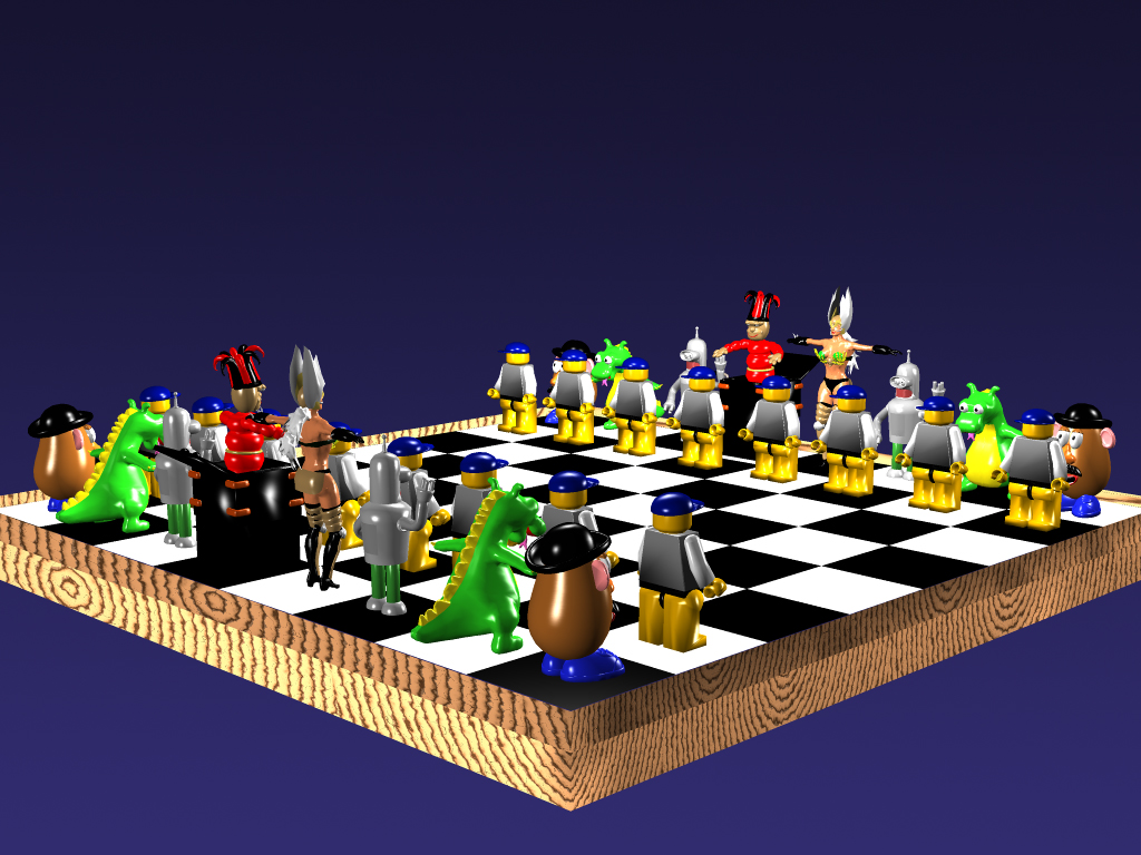
Creator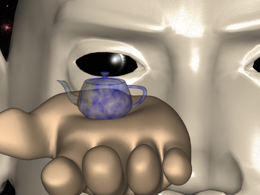
Subscribe to:
Comments (Atom)